Tutorials & Documentation
Quick Start
Introduction
Integra Live is divided into two main views: the Arrange View is for composing and experimenting with musical ideas — the Live View is for performance. To switch between the views, click the buttons in the top-left of the Integra Live window:
Integra Live also has an Info View showing info about the application and current project.
Arrange View
The Arrange View is the main view of the application. It enables audio processing blocks to be be created and arranged on a musical timeline. It also enables interactive elements to be added through the Routing and Scripting tabs in the Properties Panel.
Blocks
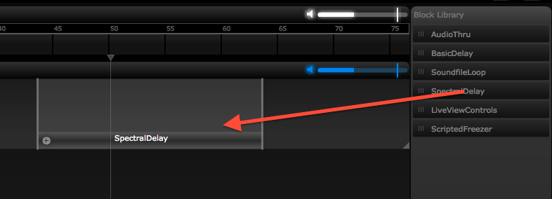
A block is a container for adding and connecting modules. blocks are used to organise modules into groupings that make musical sense. One example is the “SpectralDelay” block included in the Integra Live Block Library. This block contains a stereo soundfile player feeding into two filters and two spectral delays.
- To add a block from the Block Library, click the block name and drag it onto a track
- To add a new empty block, double-click an empty area inside a track
- To activate a block, drag the playhead so that it is horizontally aligned with the block
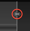
- blocks can be re-sized by click-dragging their left or right edge
Tracks
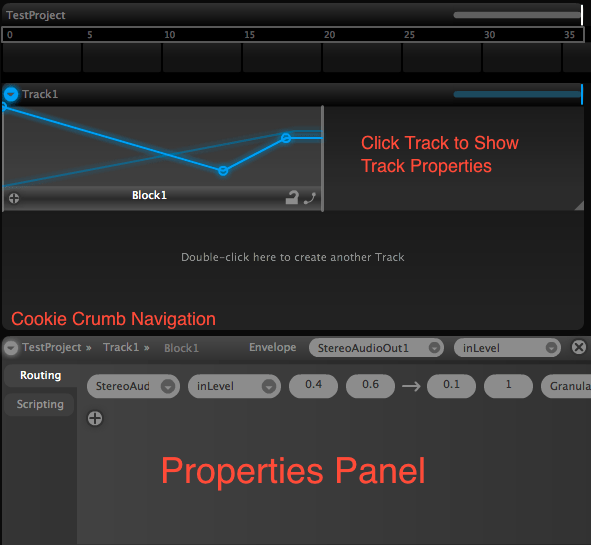
Tracks enable multiple blocks to be active at the same time.
- To add a track, double-click in the empty space under an existing track
- To vertically re-size a track click-drag the tab in the bottom-right corner
Properties Panel
The lower part of Arrange View shows a Properties Panel. This panel changes context depending on whether a block, track or entire project is selected. The Properties Panel is used to control routing, scripting and envelopes. The current project, track or block can also be selected using the “cookie crumb navigation” widget in the top-left of the Properties Panel.
Module View
The Module View is a sub-view of the Arrange View. It can be entered by double-clicking on a block.
A module can be used to process, generate or analyse musical sound in Integra Live. modules can be very simple “effects” such as delays and pitch shifters, or more sophisticated processing tools such as granular synthesisers.
Adding and connecting Modules
- To enter Module View double-click a block in Arrange View.
- To add a module to the Module View drag a module name from the Module Library to the canvas
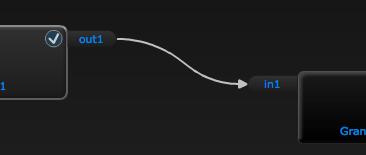
- To connect two modules, click and drag from a module output (e.g. “out1”) to a module input (e.g. “in1”)
- Dragging a module onto an existing connection, will split the connection and add the module in the signal path
- Modules and connections can be removed by selecting and then pressing “backspace”
Module Properties Panel
- Selecting a Module will cause its controls to be shown in the Module Properties Panel underneath the canvas
- Module controls (such as sliders and dials) are used to change module parameters in real-time and are interactive through clicking, dragging and text-entry
- Precise values can be entered by double-clicking the control‘s numeric value and typing the new value in the text-entry box
- MIDI learn can be enabled for a parameter by clicking the MIDI learn icon on the top left corner of the parameter’s control . Once incoming MIDI has been received, an automatic route will be created in the block‘s routing panel.
MIDI Learn
All parameters in Integra Live can be controlled via external MIDI messages, for example from a hardware MIDI device. The simplest way to set up routing between a MIDI controller and a module parameter is to use Integra Live’s MIDI learn feature.
- To use MIDI learn, first enable that the correct MIDI input device is selected in the Integra Live Preferences
- To enable MIDI learn for a parameter, in Module View select a module, then click the MIDI learn icon for a parameter in the Module Properties Panel
- The MIDI learn icon will then flash until incoming MIDI is received
- Once incoming MIDI has been received, an automatic route will be created in the block‘s routing panel
- The MIDI learn icon will change to a lock to indicate that the parameter is being controlled by an external device
- To “unlearn” a MIDI → parameter routing click the lock icon on the corresponding parameter and select “Delete Routing from MIDI.cc”
Lock Override
When a module parameter is being controlled by a source such as an envelope or an external MIDI controller, a lock icon will be shown on the parameter’s control in the Module Properties Panel. When a parameter is locked it can’t be target of another route and the control can’t be modified by clicking with the mouse.
- To temporarily override a lock hold down the
ctrlkey before clicking on the control. The parameter will be re-locked after thectrlkey is released.
Routing
In Integra Live, tracks, blocks and modules all have parameters that are used to store values representing their current settings. These values can be routed so that when a source parameter changes, the value of any target parameters also changes. This can be used to route the value of a slider on an external controller to “room size” of a reverb, or to route the value of a “play” button to another “play” button so that playback of two separate modules starts simultaneously.
- To add routing within a block, select a block, then click the Routing Tab in the Block Properties Panel, then click the “+” icon to add a new route
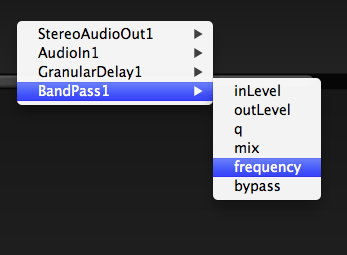
- The drop-down menus can then be used to set the source module, source parameter, target module and target parameter
- The same process can also be used for routing between blocks or tracks, by selecting the parent track or project respectively
When a route is created between two parameters, the target parameter becomes “locked”. A small lock icon will be displayed on the parameter’s control in the module properties panel indicating that it cannot be changed. To temporarily override the lock, hover over the control and hold the ctrl key.
Scripting
Integra Live has a built-in scripting facility based on the Lua programming language. Scripts can be used to set and get parameters and perform a range of procedural operations on them.
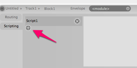
- To add scripting within a block, select a block, then click the Scripting Tab in the properties panel, then click the “+” icon to add a new script. Script can then be typed into the text-area
- Integra Script is a super-set of Lua, with the added ability to directly address Integra Live parameters using “dot notation”:
Copy to Clipboard
- Scripts can be triggered by routing any parameter to the Script “trigger” parameter
Timeline
The master timeline provides a reference point against which musical ideas can be organised. Timeline progression can be linear, where the ordering and duration of blocks corresponds to their ordering in performance, or non-linear, where the playhead moves to arbitrary points on the timeline with some blocks being activated indefinitely or stopped and started through user interaction.
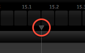
- The playhead position can be changed manually by click-dragging the control triangle
- The playhead state can be set to “play” or “pause” using the button controls in the top-left of the Arrange View
- Clicking the timeline numbering, can be used to zoom and scroll the view. Clicking and dragging left/right controls horizontal scroll, dragging up/down controls zoom level
Scenes
Scenes are used to create user-defined progressions through musical time. One application of this is to define Scenes that correspond to different sections of a musical work “Section A”, “Section B”, “Cadenza” etc. Another application is to create multiple pathways within a work as found in improvisation and “open form” composition
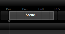
- Scenes can be added by click-dragging in the scene bar on the global timeline
- When a scene is selected, its properties are shown in the Properties Panel
- A scene can be activated by selecting it in the global timeline, or by selecting its keybinding in Live View
- A scene can have three different states when it is activated:
- Hold: The playhead will be set to pause when the scene becomes active
- Play: The playhead will be set to play when the scene becomes active
- Loop: The playhead will loop back to the beginning of the scene, when it reaches the scene end
Envelopes
Envelopes can be used to automate the control of module parameters. This can be used for creating pre-defined musical gestures resulting from multiple module parameters changing simultaneously. Another example use is to create cross-fades between sections.
- To add an envelope select a module from the modules dropdown on the Block Properties Panel:
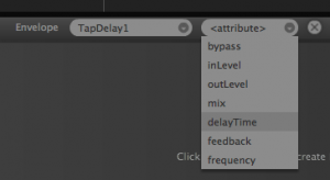
- Select the parameter to control from the parameters dropdown:
- To add control points click on the envelope line in the block:
- To delete a control point, drag it to the left until it disappears and release the mouse button.
- To select an envelope use the module and parameter dropdowns on the Block Properties Panel.
- To delete an envelope click the “x” next to the module parameter dropdown on the Block Properties Panel.
As with routing, when an envelope is created, the target parameter becomes “locked”. A small lock icon will be displayed on the parameter’s control in the module properties panel indicating that it is being controlled by an envelope cannot be changed. To temporarily override the lock, hover over the control and hold the ctrl key.
Block Toolbar
Each block has a block toolbar, which contains a number of buttons that can be used to perform actions on the block.
- To enter the Module View for a given block, click the plus sign:
- To lock a given envelope for editing click the lock button
. When the lock is closed:
only the current envelope will be selectable. When the lock is open:
any envelope can be selected by clicking on it.
- To modify the curvature of an envelope, click the curve button
. When the curve has arrow indicators , envelope curvature can be modified by clicking an envelope and dragging up or down to change the shape of the curve.
Live View
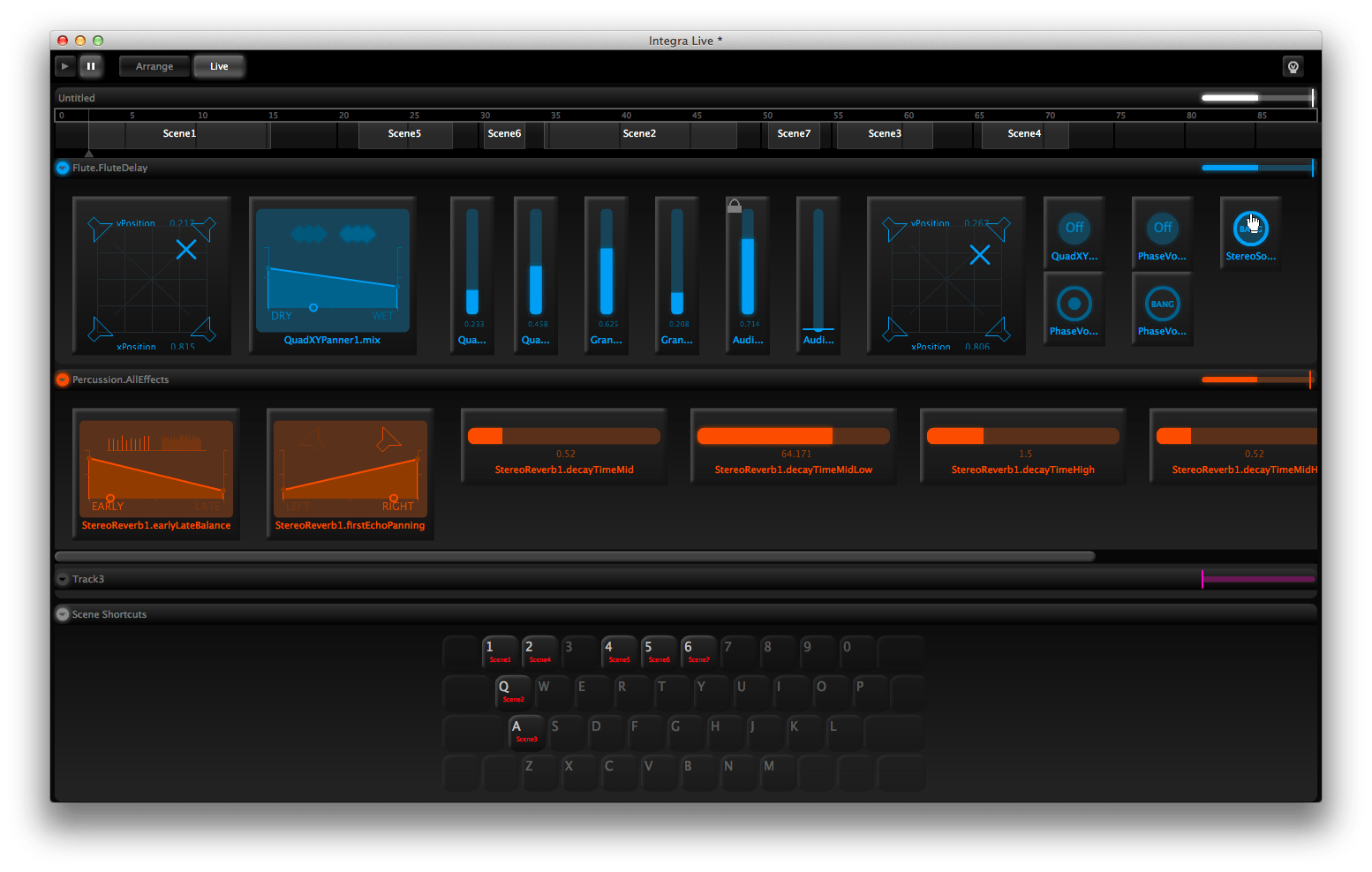
The Live View is designed for live performance. Its purpose is to provide a reduced set of module controls for each Block, with custom control sizes and layout for convenience. When in Live View the computer keyboard also becomes active for navigating between Scenes.
- Controls can be added to Live View by selecting Arrange View, clicking “+” on the relevant block, and then clicking the checkbox in the top right corner of the required controls
- An entire Module‘s controls can be added or removed from the Live View using the checkbox on each module
- Controls can also be added directly in Live View by right-clicking the canvas and selecting a control from the menu:
Scene shortcuts
- Scenes can be activated from Live View by pressing the key associated with each scene
- Scene key bindings can be reassigned by click-dragging the scene names on the Live View keyboard map
Control layout
- Controls in Live View can be moved and re-sized by click-dragging their background and edges respectively
Info View
The Info View shows information about elements in Integra Live when the cursor hovers over them.
The Info View can be shown or hidden at any time using the View menu
Adding Info
The Info View can be used to add info to projects. Info can be added to the project itself, as well as individual tracks, blocks and scenes.
To add info to an element:
- Hover the mouse over the element
- Press Control-3 (F2 on Windows) to lock the Info View
- Click the “edit” button on the Info View title bar
- Type your info into the Info panel
- Press Control-3 (F2 on Windows) to release the Info View
Info can now be viewed by hovering over the element with the cursor.
Module Management
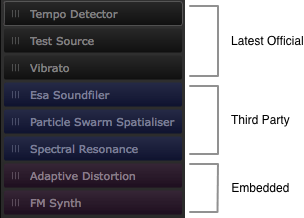
Integra Live supports three types of module:
- The Latest Official modules that come bundled with the application
- Third Party modules created by the Integra community
- Old versions of modules that are embedded in projects or blocks
To install a Third Party module:
- double-click a
.modulefile or - select Install Third Party Modules… from the File menu
This will make a copy of the module and add it to the Integra Live module library as shown below.
To uninstall a Third Party module:
- Select Module Manager from the application’s View menu
- Select the Install / Uninstall tab
- Select the module to be uninstalled from the Installed Third Party Modules listing
- Click the Uninstall button
Module Versions
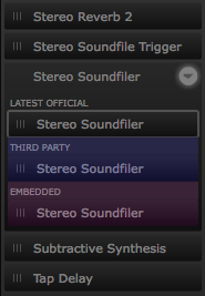
Integra Live can support multiple versions of the same module. If more than one version of a module is available, a disclosure arrow will be shown to the right of the module name in the module library. Clicking this arrow will reveal the available versions of the module. In the following listing there are three versions of the Stereo Soundfiler module available: the latest official version, a third party version and an out-of-date version embedded in the project.
To upgrade all modules in a project to the latest official version:
- Select Module Manager from the application’s View menu
- Click the Upgrade All button in the Manage Versions Tab
To switch versions for a specific module:
- Select Module Manager from the application’s View menu
- Select the module for which multiple versions are available
- Select the version to switch to from the Alternative Versions list
- Click the Switch Versions button
This will switch all instances of the module to the selected version.
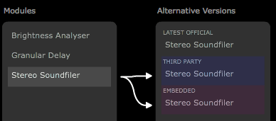
Versions currently in use within the project are indicated with arrows. The following example shows that the project contains instances of a Stereo Soundfiler module and that these instances use either a Third Party version and an out-of-date embedded version.
Typically it is best to always upgrade projects to use the latest official versions, but there may be occasions when an alternative version is required because it has characteristics not present in the official version.
Module Upgrade Dialog
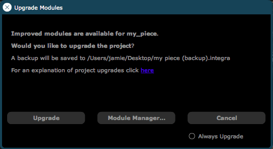
When a project, track or block is opened or imported, and improved versions of the Latest Official modules are available then Module Upgrade Dialog will be displayed.
- Click Upgrade to upgrade modules in the project, track or block to the Latest Official versions—these Latest Official versions will then be embedded in the project file and replace current instances of those modules
- Check the Always Upgrade checkbox before clicking Upgrade to always upgrade modules in future without prompting—this option can later be unchecked using the Module Manager
- Click Module Manager… to selectively upgrade specific modules
- Click Don’t Upgrade to leave the project as it is—modules can always be upgraded later using the Module Manager
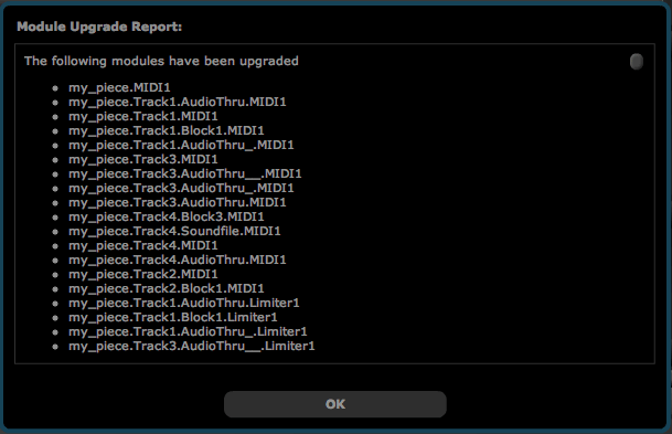
If modules are upgraded, an Upgrade Report will be shown, providing a detailed report of the changes that have been made.
In the upgrade process, Integra Live will attempt to preserve connections and parameter settings for upgraded modules. However if parameters or audio inputs and outputs have been removed or renamed in the Latest Official versions then connections to these will not be preserved. Ranges of parameters may also be altered in ways that affect the operation of the module. It is therefore good practice to keep a copy of the upgrade report and check through all upgraded module instances for issues.
When performing any upgrade, Integra Live will create a backup of the project with the file suffix (backup).integra. This can be used to revert to the pre-upgrade version of the project or can be safely deleted.
Other features
Mute Control
Projects, tracks and blocks can all be muted, making them inactive and silent.
When a track is muted, it will be greyed out as shown below.
Individual blocks can also be temporarily muted by clicking the speaker icon in Module View. This mute setting will be overridden if the block is re-activated by the global playhead.
MIDI Input Indicator
When MIDI is received by Integra Live, the MIDI Input Indicator in the top-right corner of the application window will glow.
- To view incoming MIDI note and CC values click the MIDI Input Indicator. This will display the MIDI Info panel:
If the MIDI Input Indicator fails to glow when MIDI is sent to Integra Live, check the MIDI device settings in the Integra Live preferences dialog.
Lighting
- Lighting can be set to “on” for studio use and “off” for live use in darkened environments. This is achieved by clicking the lighting icon in the top-right of the application window:
Import and export
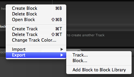
Tracks, blocks and module settings can all be exported and imported to/from disk. This enables specific components to be moved between projects. Additionally, blocks, can be added to the Block Library, which allows easy drag ‘n’ drop of exported blocks.
- Import/export is available from the context menu in Arrange View. For example to export a track, context-click the track and click “Export…→Track”
Renaming
- Tracks, blocks and modules can be renamed by double-clicking their name and typing in the text-entry box.
Scripting 1
Introduction
Scripting in Integra Live allows users to perform basic programmatic operations on module parameters such as:
- conditional evaluation
- mathematical operations such as arithmetic, trigonometry and random number generation
Integra script is a superset of the Lua programming language.
A good tutorial on the Lua language can be found here.
Module attribute semantics
The Integra scripting processor adds the following additional semantics to the basic Lua language:
Adding a script
Scripts can be added, removed and edited through the properties panel of projects, tracks or blocks in the Integra Live Arrange view. To add a script:
- Select the arrange view by clicking the button in the top-right of the screen
- Select the entity you want to add a script to, e.g.’Block1′
- Select the ‘Scripting’ tab on the left side of the Block properties panel
- Click the ‘+’ button
Hello World!
Our first script is going to add a module and play a note. In order to do this, we need to first add an “Additive Synthesiser” module to the module canvas inside Block1, and connect the AddSynth1 output to the StereoAudioOut1.
To confirm that we have audio, click the test button in the AddSynth1 properties panel. If no audio is heard, check your Audio Preferences and try again.
Once we have audio, return to the arrange view:
- select Block1
- select the scripting tab in the Block1 properties panel
- click the ‘+’ button
- click in the text area to the right of the Script1 label
You should see a flashing cursor. We are now ready to type our first script. Enter into the text area:
Executing a script
There are several ways to execute a script. The first is to manually execute it:
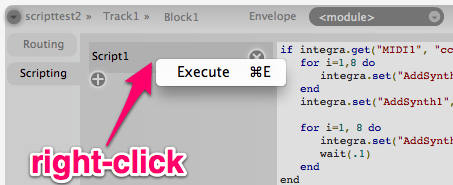
- right-click (or ctrl-click) on the script’s name tab
- select (left-click) ‘execute’ from the context menu
A simple script
In our next script, we’re going to extend our ‘Hello World’ script, so that it changes the parameters of AddSynth1 whilst the note is sounding.
In order that we can trigger our script via MIDI, we first need to connect a MIDI controller capable of emitting MIDI CC messages (e.g. when a pad is tapped) and this controller must be selected in the Integra Live Preferences dialog.
We then need to add a conditional expression to the beginning of the script. This will ensure that the Additive synthesiser is only triggered when we get a MIDI value 127, and not when we get any other value (such as zero).
This script does two things. It gets the current value of MIDI controller 4, and it then compares the result to the integer value 127 using the Lua logical comparison operator ‘==’. If the result of this comparison evaluates true then the value of AddSynth1.test gets set to 1.
We can test this now by tapping our external controller. The result should be the same as when we executed the script via the script context menu. If you don’t hear anything, check that you’ve routed MIDI1 cc4 to Script1 trigger in the Block routing panel.
Next, we are going to extend the script by adding a loop, which gradually adds partials through the duration of a note.
Once you’ve copied this into the script text area, press the MIDI pad again. You should hear a 1 second harmonic arpeggio.
Code breakdown
First we set all partials in AddSynth1 to zero, using a for loop
In pseudo-code, this is saying “for each value betwen 1 and 8, set the variable i to the new value and the set the i‘th partial to 0″. Unrolling the loop, we’d get something like:
Note: that here we are using the alternative syntax for setting the value of a module parameter. By using a string representation of the parameter name, we are able to dynamically construct module and parameter names using string variable substitution and concatenation.
Next we actually play the note, as before:
Finally, we use another loop to raise the level of each successive partial to .5 after an interval of 100ms.
This is similar to our first loop, with the key difference being inner while loop which uses Lua’s os.clock() function to pause program execution by busy looping for .1 seconds of each iteration of the outer for loop.
Introducing ‘alea’!
In our final version of the script, we’re going to use the Lua math.random() function to introduce some randomness. Instead of successively raising the level of each partial when the script is triggered, we’re going to successively set eight random partials to eight random amplitudes between zero and one.
Now, if you hit your MIDI pad, you should here a different combination of partials with each tap.
Scripting 2
Introduction
In our second scripting tutorial we will cover a few of the common scripting tasks in Integra Live.
This tutorial assumes you have already read the Scripting 1 Tutorial.
Signal path selection
In this example, we have an audio signal, and we would like to route it using scripting.
There are a number of ways to achieve this, but the most straightforward is to create a fixed network of modules and use the inLevel parameter to control signal flow to each module.
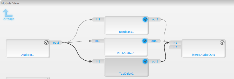
So first we need to set up a network of modules to control.
- Start a new project
- Open Block1
- Add the following network
Now, when the script is executed, the signal will pass through either TapDelay1, PitchShifter1 or BandPass1, depending on the value of the variable val. In this script val is set randomly.
Module Development Quick Start
Introduction
This is a step-by-step tutorial showing how to create a simple Tremolo module for Integra Live.
Since Integra modules are written in Pd, a basic knowledge of Pure Data is required. Developers unfamiliar with Pd should start here.
Requirements
This tutorial requires the Integra Module Creator application.
OS X: download the Module Creator.dmg, mount the DMG, and drag the “Module Creator.app” to the Applications folder.
Windows: the Module Creator is bundled with the main Integra Live installer. To install, download the Integra Live.msi, double-click the .msi file and follow the on-screen instructions. Once installed, the Module Creator will be available via the Start Menu.
Creating a Module
- Open the Module Creator
- Click File -> Import Template… -> Processors -> Processor.integra-module to load the Processor template
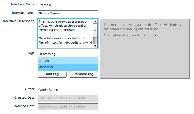
- Select the Interface Info tab in the Module Creator and enter the details as below
- Select the Endpoints tab in the Module Creator and click the Add Endpoint button
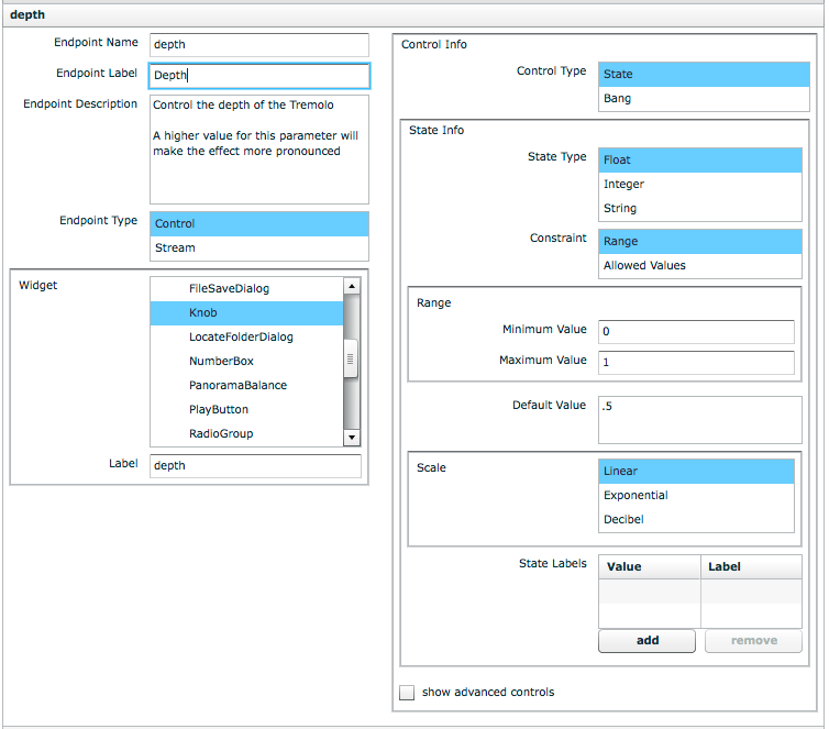
- Enter the details for a “depth” endpoint as shown below
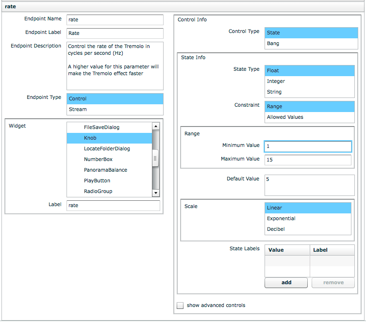
- Click the Add Endpoint button and enter the details for a “rate” endpoint as shown below
- Click the Widget Layout tab and layout the widgets as shown below
- Click Edit In Pd and open the
mono_processorsubpatch inside theMonoProcessorabstraction - Open the
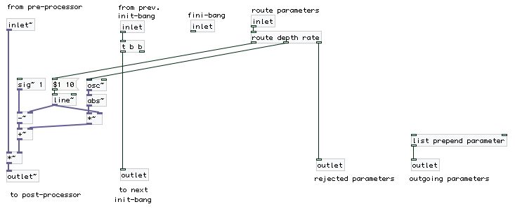
module_implementationsubpatch and add the implementation as shown below
- Save the
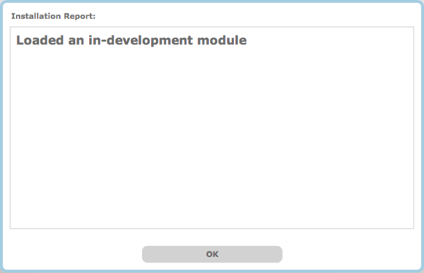
MonoProcessor.pdpatch and exit Pure Data. - Now, test the module by selecting Test In Integra Live from the Test menu in the Module Creator. Integra Live will open, with a confirmation that the module has been installed
- Click OK and double-click
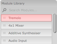
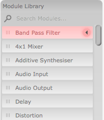
Block1to open it. The new module will now be displayed in red in the Module Library
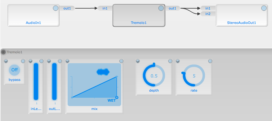
- To test the Tremolo module drag it into the Module View and connect it up as shown below
- Finally quit Integra Live and select Save As… from the File menu in the Module Creator to save the module
- The module can now be installed in Integra Live by double-clicking the module file, or by selecting Install 3rd Party Modules… from the File menu in Integra Live
More information
For more information about creating Integra modules, see the Integra Module Development Guide.
Module Development Guide
Introduction
This guide provides in-depth information on how to create modules that can be used in Integra Live. For an initial introduction see the Module Development Quick Start page.
Requirements
In order to create Integra modules, the Integra Module Creator tool is required.
On Mac OS X, download the Module Creator.dmg, mount the DMG, and drag the “Module Creator.app” to the Applications folder.
On Windows, the Module Creator is bundled with the main Integra Live installer. To install, download the Integra Live.msi, double-click the “.msi” file and follow the on-screen instructions. Once installed, the Module Creator will be available via the Start Menu.
What is a Module?
Integra modules are loadable units that can be used to process, generate or analyse audio or control signals in Integra Live. Modules can be simple “effects” such as delays and pitch shifters, or more sophisticated processing tools such as granular synthesisers.
Each module’s data is stored in a corresponding file, which can be loaded by Integra Live and installed to the user’s system. These files have the suffix “.module”, for example the module file for a Spectral Delay would be called “SpectralDelay.module”.
A Note on libIntegra
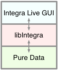
The Integra Live application is built on top of a shared library called libIntegra. libIntegra is responsible for loading modules and managing communications between the Integra Live GUI and the Integra DSP Host (based on Pure Data as well as other tasks such as saving and loading Integra project files.
Anatomy of a Module
Integra “.module” files are ZIP formatted archives with the “.zip” suffix replaced with “.module”. Module files contain all of the information required for Integra Live to generate the module’s user interface, and instantiate the module’s processing components in a DSP host.
Integra module files consist of two stored components: interface and implementation. A module’s interface defines all of the external characteristics of the module such as its name, description, tags, endpoints, widgets and widget layout. A module’s implementation defines the internal audio and control processing algorithms.
The interface is defined using the Integra Module Creator tool, and written to a file. This file, called an Integra Interface Definition (IID) is a type of XML file. The implementation for the module is defined using the Pure Data patching environment (Pd), and saved as a set of Pd patches.
When a module is loaded in Integra Live, details about the module’s interface are added to a memory-resident database. This database is used to determine which widgets are shown in the module properties panel, ranges, constraints, and the contents of the Info panel for the module. For each module instance in an Integra Live project, a corresponding instance of the module’s Pd patch is loaded in the running Pd host.
Module Endpoints
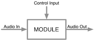
The module interface contains a schematic description of one or more endpoints. An endpoint is a connectable attribute that can be of type Control or Stream. Control endpoints define parameters such as “delay time” or “frequency”. Stream endpoints define audio inputs and outputs. The information included in the endpoint definitions enable Integra Live to determine which parameters to show in the routing view menus and which control widgets to show in the Module Properties panel.
Control endpoints can of type State or Bang. State endpoints are associated with a value that represents the current state of a parameter. This value changes in response to external inputs (such as MIDI), internal timers and scheduled processing or as a result of two or more endpoints being connected. Endpoint state is saved by Integra Live when projects are saved, or when tracks, blocks or modules are exported and is restored when they are loaded.
Control endpoints of type Bang are stateless and send a valueless signal to any connected endpoints when triggered (via a GUI widget, a connected endpoint or the module’s implementation).
Creating a new Module Interface
We encourage module developers to consider carefully their module’s interface before creating the module implementation.
Developers should normally develop their interface first, refactoring it if needed after they have created their implementation in Pure Data.
Import Template…
The Module Creator comes with a selection of templates covering the most common types of module. Templates can be imported via File > Import Template….
Templates provide a base-level interface for performing audio input and / or output and endpoints for “active”, “bypass”, “mix”, “inLevel”, “outLevel” and “mute” where appropriate. Most of the modules in the Integra Live Module Library are based on one of these templates.
In addition to the Templates provided with the Module Creator, developers can import any other module as a Template by selecting Import Template -> Browse…
Interface Info
When the Module Creator is first opened, the Interface Info tab is active. Interface Info has one compulsory field (Interface Name), and a number of optional fields. Hovering over each field with cursor will show a tooltip explanation for each field.
We encourage module developers to use a short easily identifiable Interface Name
Naming conventions for modules are as follows:
- Stereo* — the module has exactly two outputs and zero or more inputs OR exactly two inputs and zero or more outputs
- Quad* — the module has exactly four outputs and zero or more inputs OR exactly four inputs and zero or more outputs
- Octo* — the module has exactly eight outputs and zero or more inputs OR exactly eight inputs and zero or more outputs
No special prefix is used for other input / output configurations. For example a bandpass filter with one input and one output would simply be called BandPass or BandPassFilter.
Interface Label should contain a short human-readable version of the Interface Name. Interface Labels are used construct the module library and module info view panels in Integra Live. For example, the Interface Label for the “BandPass” module is “Band Pass Filter”.
Interface Description should describe what the module does in simple language. Technical terminology should be kept to a minimum. The Interface Description field can be written in Markdown, and a preview of this is shown to the right of the text entry panel. The contents of this field are used to generate the module info panel contents in Integra Live.
We encourage module developers to consult the documentation guidelines for further details
A completed Interface Info is shown below along with a preview of the Interface Description field.
Tags should define a set of words used to categorise the module. These are used to construct the Tags filter box in the Module List in Integra Live.
A number of pre-defined tags are provided in the module creator. To use non-listed tags, click “add tag” and type directly at the cursor.
Endpoints
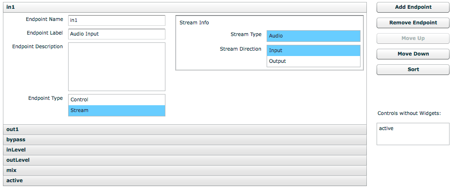
Clicking the Endpoints tab in the Module Creator enables interface info for one or more endpoints to be added. To add an Endpoint, click the Add Endpoint button
As Endpoints are added, they are shown in an accordion-style view, where each Endpoint can be revealed by clicking its title bar. Endpoints can be removed, moved or sorted using the button panel on the right.
Each Endpoint has one compulsory field (Endpoint Name), and a number of optional fields. Hovering over each field with cursor will show a tooltip explanation for that field.
Endpoint Name must be in lower camel case without special characters. Endpoint Names are used in the Routing and Scripting panels as well as for control labels in the Module Properties and Live views.
We encourage module developers to use a short easily identifiable Endpoint Name
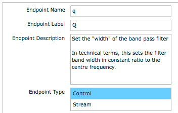
Endpoint Label should contain a short human-readable version of the Endpoint Name. Endpoint Labels are used construct the Info panels for module parameters in Integra Live. For example, the Endpoint Name “inLevel” might be given an Endpoint Label “Input Level”.
Endpoint Description should describe what the module does in simple language. Technical terminology should be kept to a minimum. The Endpoint Description field can be written in Markdown, with a preview shown to the right of the text entry panel. The contents of this field are used to generate the parameter info panel contents in Integra Live.
We encourage module developers to consult the documentation guidelines for further details
A completed Endpoint Info is shown below.
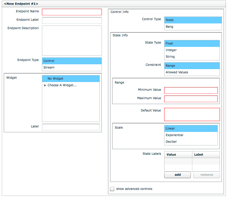
Endpoint Type defines whether the Endpoint is a Control parameter such as “delay time” or “frequency”, or a Stream such as an audio input or output. When Stream is selected, the Stream Direction must be specified as Input or Output in the Stream Info box. When Control is selected, many other options are available as explained below.
Widget is used to optionally define a Widget that is assigned to a Control endpoint. Each Endpoint may only have one widget, however, one widget can be assigned to multiple endpoints. For example an XYScratchPad widget has an “x” and “y” axis, and these axes can be assigned to different endpoints such as “pitch” and ”position”. In the case of widgets with multiple outputs, the widget control provides submenus to specify how Widgets should be shared between Endpoints.
Control Info is used to provide a more detailed definition of Control Endpoints.
Control Type can either be State or Bang. Bang should be selected for endpoints that correspond to trigger parameters such as “play” or “stop”. State should be selected for parameters that have a value associated with them such as “delayTime” or “frequency”. When State is selected then the State Info box will be displayed.
State Info ⇒ State Type is used to define the type of value that can be stored for the endpoint. Types supported by Integra are Float (32-bit), Integer (32-bit) and String.
State Info ⇒ Constraint is a compulsory field for State Control Endpoints, and is used to define a constraint that is applied to the endpoint. This can be a range, or a set of allowed values, both of which restrict the possible values that can be assigned to the endpoint. Endpoint Constraints are used by Integra Live to determine the visual appearance and behaviour of Control Widgets.
Range is a compulsory field for State Control Endpoints where the Range state is defined in State Info ⇒ Constraint.
Range ⇒ Minimum Value / Maximum Value are used to constrain the bounds of State Control Endpoints of type Integer or Float. For example, a low-pass filter module might have a “frequency” endpoint with Range ⇒ Minimum Value of 20 and a Range ⇒ Maximum Value of 18000 (measured in Hz).
Range ⇒ Minimum Length / Maximum Length are used to constrain the bounds of State Control Endpoints of type String. For example, a sound file player module might have a “path” endpoint with a Range ⇒ Minimum Length of 1 and a Range ⇒ Maximum Length of 1024.
Allowed Values are used to constrain the possible values an Endpoint can to take, to a specific set of integer, floating point values or strings. For example a “window size” endpoint could have Allowed Values of 64, 128, 256, 512, 1024 and 2048.
Default Value is a compulsory field that defines the initial value an Endpoint is set to when a module is first instantiated. The Default Value must conform to any Endpoint Constraints.
State Labels are optional and define a set of Value/Label pairs. These can be used to label values at certain points on a Control Widget’s range. For example: for a “pan” Endpoint, a Value of “-1” could be labelled “left”, “0” — “centre” and “1” — “right”.
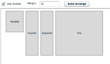
Widget Layout
Clicking the Widget Layout tab in the Module Creator enables Widgets for Endpoints to be resized and arranged graphically. This will determine the layout of Control Widgets in Integra Live’s Module Properties panel.
Implementation
Clicking the Implementation tab in the Module Creator enables the module implementation to be added or edited using Pure Data (Pd).
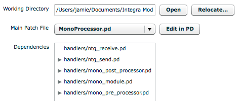
The module implementation’s files will be unpacked into a temporary working directory (~/Documents/Integra Module Creator on Mac). This can be relocated by clicking the Relocate… button.
Missing Pd ‘objects’ (externals or abstractions) will be listed in a Missing Objects box, and unused files listed in an Unused Files box.
Developers are encouraged to delete all Unused Files before saving unless they are explicitly required (e.g. in the case of a README or data file)
Editing the Pd Patch
The Pd patch for module implementations can be edited by clicking the Edit In Pd button in the Implementation tab of the Module Creator. This will open up a Pd window containing some controls for module endpoints under the heading Test Module Parameters.
The patch that opens when Edit In Pd is clicked is a host patch. To open a module implementation, click the toggle under Show / Hide Module. This will open the top-level Pd patch for the module.
The module is required to provide audio inlets and outlets for each Audio Stream Endpoint, and to respond to messages from libIntegra using the receive symbol integra-broadcast-receive, followed by a [route $1] to route only messages designated for this instance. When using one of the Templates included with the Module Creator, this boilerplate is provided by the [handlers/ntg_receive] abstraction.
Developers are strongly encouraged to use one of the provided templates rather than starting their module from scratch
The [handlers/ntg_receive] abstraction provides three outlets:
- The right-most outlet passes messages with selectors corresponding to Endpoint names, and values corresponding to Endpoint values, e.g. ‘frequency 300’, ‘delayTime 1.2’
- The centre outlet passes a ‘fini’
bangdirectly before the object is deleted - The left-most outlet passes a ‘init’
bangimmediately after the object is added to the canvas
The messages from the outlet should be handled by a [route] object, e.g. [route frequency delayTime] to pass control messages into the DSP. The ‘init‘ and ‘fini’ bang messages should be used for any initialisation or cleanup that needs to be done on the patch.
The actual implementation of the module’s functionality should be as minimal as feasibly possible.
Developers should not add range checking and checks for legal values to their modules as these are enforced by libIntegra using Constraints specified in the Interface Definition.
Developers are discouraged from adding high-level documentation in the comments of their Pd patch especially when it duplicates aspects of the interface definition.
When patch editing is complete, the top-level Pd patch for the module should be saved and the Pd application can be closed.
By convention top-level Pd patches for modules are named .pd for example a SpectralDelay module would have a top-level patch called SpectralDelay.pd
NOTE: Behind the scenes Integra Live creates one instance of your Pd implementation per module instance. Therefore any Pd sends and receives that need to be instance-specific should be prefixed with a $0, e.g. [r $0-test]
Sending Values to libIntegra
Sometimes a module implementation will need to send values back to libIntegra, for example so that the current value of a VU meter can be displayed, or so that the state of a “playPosition” endpoint can be updated. In order to send values back to libIntegra, messages must be sent to the integra receive symbol using [s integra]. The message format for sending these values is:
e.g.
If using one of the implementation Templates provided with the Module Creator, it is sufficient to simply pass pairs to the [handlers/ntg_send $1] abstraction instance.
Values sent to libIntegra will be posted to the Pd console for debugging purposes.
Developers are encouraged to use one of the provided templates rather than starting their module from scratch
Saving Files
If the module implementation loads files, and this file loading is exposed to the user, the module is responsible for persisting these files. For example, if a soundfile player supports a ‘openFile’ String Endpoint, which gets passed a string representing a path to a soundfile by a SoundFileLoadDialog Widget, then the implementation must ensure the loaded file is available next time the module instance is loaded.
In order to achieve this the module implementation must do three things:
- The special endpoint “dataDirectory” must be included in the Interface Definition. It must be defined as a Control endpoint with Control Type: State; State Type: String; and Range: 0…1024. Can Be Source and Can Be Target must also be unchecked under “show advanced controls” in the bottom right of the “dataDirectory” Endpoint panel under the Endpoints tab.
- The endpoint used to pass the file path must have Is Input File checked under “show advanced controls”. For example if an endpoint named “openFile” is used to store the path, this endpoint must have Is Input File checked
- The implementation must provide the necessary logic to restore the saved file from the data directory when the module instance is created
Saving Files from Pd
If a “dataDirectory” endpoint has been correctly defined in the Interface Definition of a module, libIntegra will set the value of this endpoint to the path to a temporary directory at runtime.
This data directory should be used by the module implementation for saving files.
Developers should only use the provided data directory for saving files used by the module. No other location should be used as this will result in data not being included in Integra Project files.
When a Project is saved (or a Track, Block or Module) is exported in Integra Live, libIntegra bundles up the contents of each module’s data directory (if there is one), and saves it inside the “.integra” file. When the “.integra” file is next loaded, the data directory gets unpacked to a temporary location and the value of the “dataDirectory” Endpoint for the corresponding module gets set to this location.
Therefore if a module instance saves and audio file to /audio.wav, the Integra Live Project is saved and then reloaded on a different computer, the module instance can expect to find audio.wav in the path its “dataDirectory” Endpoint is set to.
For a working example of how to implement file save / load for a module developers should inspect the StereoSoundfileTrigger module distributed with Integra Live
NOTE: the value of a “dataDirectory” Endpoint will not get set by libIntegra in the Pd module host provided by the Module Creator (i.e. when Edit In Pd is clicked) in order to test file saving functionality, the module must be tested in Integra Live
Advanced Controls
The Endpoint schema for Integra Interface Definitions has a number of advanced fields, which can be accessed through each Endpoint’s panel in the Endpoints tab of the Module Creator.
Is Saved to File defines whether the state of the Endpoint is saved to file when a save operation is performed by libIntegra. The default is for Is Saved to File to be checked. However, if the Endpoint is storing transient data that shouldn’t be persisted between saves, Is Saved to File should be unchecked. An example would be a “currentPitch” on a pitch detector module where the value of “currentPitch” could be obsolete if a live input is connected to the pitch detector.
Is Input File should be checked if the Endpoint is used to pass the path of a file to be loaded by the implementation. When Is Input File is checked, libIntegra creates a temporary data directory for the module, copies the file into this directory, and passes the new path of the file inside the data directory to the implementation. An example would be an “openFile” endpoint on a soundfile player — usually this would also be assigned a SoundFileDialog Widget.
Can Be Source / Can Be Target define whether the Endpoint can be the source and / or target of a connection. Both of these options are checked by default enabling the Endpoint to be connected to other endpoints by libIntegra. Integra Live also uses this field to construct the contents of the dropdown menus in the Routing panel. If Can Be Source is unchecked, the Endpoint will not be available as a source in the Routing panel, if Can Be Target is unchecked, the Endpoint will not be available as a target.
Testing in Integra Live
Modules can be tested in Integra Live without separately loading Integra Live and installing the module. To test a module in Integra Live from the Module Creator, select Test In Integra Live from the Module Creator’s Test menu. This will open a copy of Integra Live and temporarily install your module.
The module will then be accessible via the Module Library in Module View (accessible by double-clicking Block1). In-development modules appear at the top of the Module List, highlighted in red.
Henrik Frisk’s Scripting Screencast no. 1
Henrik Frisk’s Scripting Screencast no. 2
Further support
If you have any further questions, feature requests or bug reports, please use our contact form.
